Search Sites

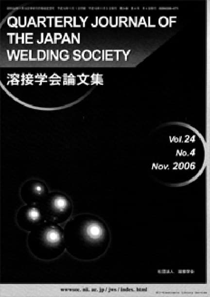
QUARTERLY JOURNAL OF THE JAPAN WELDING SOCIETY Vol. 2 (1984), No. 4

ISIJ International
belloff
ONLINE ISSN:
PRINT ISSN: 0288-4771
Publisher: JAPAN WELDING SOCIETY

Backnumber

  1. Vol. 42 (2024)

  2. Vol. 41 (2023)

  3. Vol. 40 (2022)

  4. Vol. 39 (2021)

  5. Vol. 38 (2020)

  6. Vol. 37 (2019)

  7. Vol. 36 (2018)

  8. Vol. 35 (2017)

  9. Vol. 34 (2016)

  10. Vol. 33 (2015)

  11. Vol. 32.2 (2014)

  12. Vol. 32 (2014)

  13. Vol. 31 (2013)

  14. Vol. 30 (2012)

  15. Vol. 29 (2011)

  16. Vol. 28 (2010)

  17. Vol. 27 (2009)

  18. Vol. 26 (2008)

  19. Vol. 25 (2007)

  20. Vol. 24 (2006)

  21. Vol. 23 (2005)

  22. Vol. 22 (2004)

  23. Vol. 21 (2003)

  24. Vol. 20 (2002)

  25. Vol. 19 (2001)

  26. Vol. 18 (2000)

  27. Vol. 17 (1999)

  28. Vol. 16 (1998)

  29. Vol. 15 (1997)

  30. Vol. 14 (1996)

  31. Vol. 13 (1995)

  32. Vol. 12 (1994)

  33. Vol. 11 (1993)

  34. Vol. 10 (1992)

  35. Vol. 9 (1991)

  36. Vol. 8 (1990)

  37. Vol. 7 (1989)

  38. Vol. 6 (1988)

  39. Vol. 5 (1987)

  40. Vol. 4 (1986)

  41. Vol. 3 (1985)

  42. Vol. 2 (1984)

  43. Vol. 1 (1983)

QUARTERLY JOURNAL OF THE JAPAN WELDING SOCIETY Vol. 2 (1984), No. 4

Hcat Contents and Temperaturc of Metal Droplets in Pulsed MIG Welding

Hiroshi Maruo, Yoshinori Hirata, Yoshitaka Noda

pp. 573-578

Abstract

Heat contents of metal droplets in MIG welding are investigated for both cases, pulsed and constant current, using analogue transistor power source. From the measurement of heat content of metal droplets temperature of metal droplets is also evaluated taking account of heat loss due to radiative and conductive heat transfer between droplets and surrounding atmosphere during their flight into the calorimeter. Results obtained are summarized as follows;
(1) Among the electrode materials, used in this experiment, mild steel, stainless steel and copper alloy, heat contents of mild steel is observed to be highest, copper alloy lowest. In case of constant current MIG arc, heat contents of any materials increase as the current become higher, so far as globular transfer mode occurred. But when spray transfer mode is established, heat contents become almost constant.
(2) Heat contents of metal droplets in pulsed current type are slightly higher than those in constant current one, and are dependent on the average current used. Under such condition that spray transfer occurs syncronously with the current pulse, heat contents of droplets are nearly equal to that in constant current of peak current level.
(3) In MIG welding of mild steel, stainless steel and copper alloy, temperature of metal droplets in low current level of 30 amp. are estimated to be little higher above melting point of each material, but reach about 2000°C in current range higher than 200 amp.

Readers Who Read This Article Also Read

Bookmark

Share it with SNS

Article Title

Hcat Contents and Temperaturc of Metal Droplets in Pulsed MIG Welding

Local Flashing Phenomena of Metal Sheets

Kinji Tanuma, Osamu Ohashi

pp. 578-584

Abstract

In previous studies, the total flashing phenomena of the specimen to be welded have been discussed from the waveforms of flashing voltage and flashing current of the steel sheets.
The purpose of this study is to examine the flashing phenomena of limited part of the specimen to be welded. The materials used are of carbon steels, copper and aluminum sheets. The local flashing phenomena of the specimen to be welded are detected by the intensity of the light from the part through the slit of 1.2 mm width placed in 7 mm from the welds. The following results are obtained.
1. The local flashing is a discontinuous phenomenon, namely the flashing of several times occur at intervals of 1 or 2 ms after the flashing off of 10 up to 40 ms or 40 ms and over.
2. Such a periodical flashing is extensively in evidence during the flashing of low or medium carbon steel, copper and aluminum.
3. There is a secondary no load voltage that makes the maximum number of local flash times. The voltage is of about 6 volt in this experiment of low carbon steel sheet.
4. The mechanical properties of the welded joint of low carbon steel sheet can not attain to the excellent results under the conditions of the secondary no load voltage that makes the maximum number of local flash times.
5. There is risk of upsetting the several parts of the specimen after the flashing off of more than 10 ms, even if the carbon steel sheets are welded under the optimum welding conditions.

Readers Who Read This Article Also Read

Bookmark

Share it with SNS

Article Title

Local Flashing Phenomena of Metal Sheets

CO2 Arc Spot Welding in Steel (Rept. III)

Hidehiko Ono

pp. 584-589

Abstract

In the previous paper, empirical formulas that estimate shear tensile foce of spot weld and dimensions of nugget cross-section from both welding conditions (welding current, arc voltage, arc time) and upper plate thickness were obtained for CO2 arc spot welds in steel. These empirical formulas are valid when the gap between upper plate and lower plate is zero. However, in practice, some gap will exist in the weld joint because the force applied to press the plates together is weak.
In this paper, in order to study how the gap affects shear tensile force of weld joint and dimensions of nugget, arc spot weld joints were made using different gaps and the nugget dimensions and shear tensile force were measured. These experimental results were compared with values estimated using the empirical formulas, and the maximum gap width that could be allowed in practice was obtained.
The results are summarized as follows;
1) When the gap exceeds 1 mm, button dia. decreases with increasing gap width.
2) Nugget dia. increases with increasing gap width.
3) Shear tensile force of weld joint increases with increasing gap width. However, when the gap becomes wide and a hole appears in the center of the button, it decreases suddenly.
4) The relationship between the practically allowable gap width and the upper plate thickness has been shown graphically.

Readers Who Read This Article Also Read

Bookmark

Share it with SNS

Article Title

CO2 Arc Spot Welding in Steel (Rept. III)

A Study on Formation of Alloyed Layer of Low Melting Temperature on Bonding Surface of IN738LC with CO2 Laser

Takao Funamoto, Satoshi Kokura, Hiroshi Wachi, Mitsuo Kato, Tomohiko Shida, Masahisa Inagaki

pp. 590-594

Abstract

Diffusion welding method using alloyed layer of low melting temperature on bonding surface of IN 738LC with CO2 laser has been studied.
In this report, effect of laser beam irradiating condition on formation of alloyed layer, measurement of melting temperature and boride precipitates of the alloyed layer were investigated.
The results indicated that homogeneous alloyed layer was obtained by irradiating linearly focused laser beam (Output: 1.8 kW, Scanning Speed: 0.3 m/min) on bonding surface coated with BNi-2 powder (grain size: 74-105μm). The alloyed layer was about 300μm in thickness, melting temperature of the alloyed layer was about 1170°C.

Readers Who Read This Article Also Read

Bookmark

Share it with SNS

Article Title

A Study on Formation of Alloyed Layer of Low Melting Temperature on Bonding Surface of IN738LC with CO2 Laser

Diffusion Weldability of IN 738 LC with Alloyed Layer on Bonding Surface by CO2 Laser

Takao Funamoto, Satoshi Kokura, Hiroshi Wachi, Mitsuo Kato, Tomohiko Shida, Masahisa Inagaki

pp. 594-599

Abstract

Diffusion welding method using alloyed layer of low melting temperature on bonding surface of IN 738LC with CO2 laser has been studied.
In this report, diffusion weldability of IN738LC with alloyed surface layer was investigated. Alloyed layer was formed by irradiating linearly focused laser beam (Output: 1.8 kW, Scanning Speed: 0.3 m/min) on bonding surface coated with BNi-2 powder (grain size: 74-105μm). After alloyed layer was formed on one specimen, the specimen was bonded to an unalloyed IN738LC specimen under various diffusion welding time and diffusion treatment time. Effect of diffusion welding time was evaluated by direct observation of the isothermal solidification area of the alloyed surface at 1200°C. Observation of microstructures and microanalysis in cross sections were conducted, and the joint strengths were measured.
The results showed that suitable weldment was obtained by using the following condition; welding time 1 hour at 1200°C and diffusion treatment time 10 hours or more.

Readers Who Read This Article Also Read

Bookmark

Share it with SNS

Article Title

Diffusion Weldability of IN 738 LC with Alloyed Layer on Bonding Surface by CO2 Laser

Diffusion Welding of Al-Cu-Mg Series 2017 Alloy

Toshio Enjo, Kenji Ikeuchi

pp. 599-605

Abstract

An investigation has been made of the diffusion welding of 2017 aluminum alloy which is very difficult to join by the conventional fusion-welding technique. In the present investigation the diffusion welding has been carried out in the temperature range above the solidus line where solid and liquid phases coexist, though it is a kind of solid-state welding. The purpose for this is to aid the intimate contact and the disruption of the tenacious oxide film at the bond interface by the formation of the liquid phase.
As a result, the joint strength increased largely with raising the welding temperature above the solidus line and became much higher than that of the joint welded below the solidus line. The maximum tensile strength in the as-welded state, which was obtained at the welding temperature of 853K, was 270 MPa. It was observed with high-temperature-optical microscope that the liquid phase formed preferentially at the bond interface as well as at the grain boundary in the range between the solidus and liquidus lines. These results indicate that the liquid phase forming preferentially at the bond interface promoted effectively the bond process of diffusion welding. The maximum tensile strength was obtained when the volume fraction of the liquid phase was 2-3%.
However, when the volume fraction of the liquid phase exceeded 3%, the joint strength decreased remarkably with the increase in the volume fraction of the liquid phase. In the joint welded with the liquid phase more than 3%, many porosities were observed at grain boundaries, and the degree of welding deformation, which was estimated from the increase in the cross-sectional area at the bond interface, became much higher than that of the joint having the maximum strength. The formation of these porosities is considered to be responsible for the decrease in the joint strength. The formation mechanism of the porosity is explained as follows: In the range between the solidus and liquidus lines, the liquid phase formed preferentially at the grain boundary, and so the strength of the grain boundary decreased rapidly with the increase in the liquid phase. Therefore, when the fraction of the liquid phase exceeded a critical value (-3%), the welding deformation of base metal caused cracks at grain boundaries. The crack which was not filled with the liquid phase is considered to remain as a porosity at the grian boundary.
The tensile strength of the joint welded at 853K was increased to 400 MPa by a post-welding heat treatment consisting of ageing for 103 ks at room temperature subsequent to a water quenching from 773K.

Readers Who Read This Article Also Read

Bookmark

Share it with SNS

Article Title

Diffusion Welding of Al-Cu-Mg Series 2017 Alloy

Deposit Mechanism of Columnar Fe-Cu-C Alloy in Cu Brazing to Dissimilar C Steels

Hirohiko Ohmura, Tohru Yoshida

pp. 605-612

Abstract

Authors have already reported that in the Cu brazing to dissimilar C steels a "dissolution and deposit of base metal" took place —that is, the low C steel base metal dissolves into molten Cu filler metal and, simultaneously, the dissolved Fe deposits as the columnar Fe-Cu-C alloy phase from the high C steel boundary at a constant brazing temperature.
In this paper, the deposit mechanism of the columnar Fe-Cu-C alloy was investigated and results obtained were as follows;
(1) The columnar Fe-Cu-C alloy consists of 9 to 12%Cu, I to 2%C and the rest Fe.
(2) When C steel dissolves into molten Cu, the Fe and C atoms will form the massive Fe-C associated compound.
(3) The deposit of the columnar Fe-Cu-C alloy will be caused by that the low C Fe-C associated compound, which is dissolved into molten Cu from the low C steel, combines with C at the high C steel boundary to convert into the high C Fe-C associated compound due to larger bonding force of Fe-C compared with that of Fe-Cu in liquid Cu and its concentration exceeds the equilibrium quantity.

Bookmark

Share it with SNS

Article Title

Deposit Mechanism of Columnar Fe-Cu-C Alloy in Cu Brazing to Dissimilar C Steels

Electron Beam Welding with Filler Wire (Report 1)

Susumu Tsukamoto, Hirosada Irie, Michio Inagaki, Tatsuya Hashimoto

pp. 613-618

Abstract

In general use, electron beam welding has been executed without a filler wire. It is recommendable, however, to use the filler wire in such case as the improvement of the property of the weld metal or filling up large joint gap. In the former case, it is indispensable that the filler metal is distributed uniformly throughout the weld metal. Then, the authors investigated effects of several welding parameters on the distribution of the filler metal and discussed the selection of the welding conditions to obtain the uniform distribution of the filler metal. The results obtained are as follows.
1) In order to feed the filler metal into the root portion of weld bead, it is recommendable to select the high welding speed and the defocused condition of the beam so as the beam cavity to be opened widely at the surface.
2) As the heat input becomes larger, the filler metal is apt to be distributed uniformly in the weld metal.
3) The transverse beam oscillation at low frequency is effective for mixing the molten metal.
4) When the full penetration welding was carried out with the filler wire, the filler metal was hardly contained in the back side bead.

Bookmark

Share it with SNS

Article Title

Electron Beam Welding with Filler Wire (Report 1)

The Study of Passing Current in Contact-tip on CO2 Arc Welding

Todaaki Yamada, Keiichiro Hirakoso, Hiroshi Fujisaki, Tamotsu Kaneko

pp. 619-624

Abstract

Sincee a phenomena in wire feeding, when the arc current passed through a semi-automatic wire feed system had been previously reported, in this report, the several experiments in connection with electric phenomena in the contact-tip had been conducted. The results were as follows. The contact point exists at the top of the contact-tip. The contact voltage drop between the wire and contact-tip is about 1 volt. Usually, the wire touches the contact-tip and the current doesn't create sparks. But, it is fact that sometimes the wire doesn't touch the inner surface of the contact-tip in limited conditions. On the wire surface, various patterns can beobserved, for example, rough surface, melting spot etc. It was assumed that these surface patterns are made by electric joule heat passing from wire to contact-tip.

Bookmark

Share it with SNS

Article Title

The Study of Passing Current in Contact-tip on CO2 Arc Welding

Arc Welding of Mild Steel in Pressurized CO2 Atmospheres

Takeshi Kuwana, Ryuji Kiguchi

pp. 625-632

Abstract

Mild steel was welded in pressurized CO2 atmospheres in the pressure range from 1 to 30 atm using a solid wire of 1.6 mm dia. The effect of ambient pressure on the melting rate of electrode wire, and the geometry, chemical compositions and mechanical properties of weld metals were studied.
The results obtained are as follows:
1) The melting rate of an electrode wire increases with the increase of ambient pressure up to a certain pressure.
2) The bead width decreases with the increase of ambient pressure.
3) The penetration depth and fused area of base metals increase with increasing the ambient pressure up to a certain pressure.
4) The melting rate of electrode wire and bead geometry appear to be affected with the metal transfer mode of electrode wire in pressurized CO2 atmospheres.
5) Oxygen content of weld metals increase with the increase of ambient pressure.
6) The charpy impact values of weld metals decrease with increasing the ambient pressure.

Readers Who Read This Article Also Read

Bookmark

Share it with SNS

Article Title

Arc Welding of Mild Steel in Pressurized CO2 Atmospheres

Automatic Gouging by Air Caobon-Arc Method (Report 2)

Noboru Kimata, Shozaburo Ohta, Hidenori Suzaki, Tetsuro Miura

pp. 632-638

Abstract

Mild steel was welded in pressurized CO2 atmospheres in the pressure range from I to 30 atm using a solid wire of 1.6 mm dia. The effect of ambient pressure on the melting rate of electrode wire, and the geometry, chemical compositions and mechanical properties of weld metals were studied.
The results obtained are as follows:
1) The melting rate of an electrode wire increases with the increase of ambient pressure up to a certain pressure.
2) The bead width decreases with the increase of ambient pressure.
3) The penetration depth and fused area of base metals increase with increasing the ambient pressure up to a certain pressure.
4) The melting rate of electrode wire and bead geometry appear to be affected with the metal transfer mode of electrode wire in pressurized CO2 atmospheres.
5) Oxygen content of weld metals increase with the increase of ambient pressure.
6) The charpy impact values of weld metals decrease with increasing the ambient pressure.

Bookmark

Share it with SNS

Article Title

Automatic Gouging by Air Caobon-Arc Method (Report 2)

Fume Generation in CO2 Arc Welding by Flux-cored Wire

Tetsuo Suga, Minoru Kobayashi

pp. 638-645

Abstract

The effects of welding parameters and wire compositions on the fume emission rate of CO2 arc welding by flux-cored wire, have been studied. In addition, high-speed photographs of the welding arcs have been observed in relation to an investigation of fume generation mechanism.
As the welding current and arc voltage are raised the fume emission rate increases, while it drops as tip-plate distance is increased. Addition of argon gas in CO2 shielding gas is effective in the reduction of fume. The mechanism of the above phenomena can be generally explained on the basis of the fume formation mechanism previously proposed.
Increase of TiO2, Fe-Si and Al2O3 or decrease of CaF2 content in the flux, decreases the fume emission rate. The influence of iron power and Fe-Mn content is almost none. These variations of fume generation can be mainly explained by the vapor pressure of flux constituents.
The decrease of C content in the wire, especially in the wire sheath and lubricant, has an epochal effect in the reduction of fume. The reason of this phenomenon seems to be the restraint of the CO gas explosion in the droplets suspended at the tip of the wire.

Bookmark

Share it with SNS

Article Title

Fume Generation in CO2 Arc Welding by Flux-cored Wire

Effect of Flux Grain Size on the Bead Appearance in Submerged Arc Welding

Masaharu Kumagai, Naoki Okuda

pp. 645-652

Abstract

The effect of flux grain size on the weld bead appearance was investigated using a series of SiO2-MnO fused type fluxes with various grain sizes. And gas permeability characteristics of model flux bed was measured in room temperature and high temperature to consider the degassing behaviour from an arc cavity.
When the finer flux was used, the finer weld bead ripples was generally obtained. And the effect of grain size on the bead appearance reduced with an increase in SiO2/MnO. Gas permeability decreased with decrease of the grain size unless fluidized. And if fluidization occurs at room temperature due to the character of fine flux, considerable variation in permeability appears without any reduction of the permeability. When the flux was held at nearly its melting point in gas flow assuming the flux on an arc cavity, the permeability decreased considerably with holding time. But especially in case of fine flux, the fluidization was not stopped and moreover the permeability increased obviously within a short time by forming holes in the adhered flux bed.
It seems that the degassing behaviour out of the arc cavity has heavy influence on the bead ripple roughness relating pulsating state of the molten pool. And in case of coarse flux, irregular degassing which is compelled by the bonded layer of the flux grains surrounding the are cavity, result in rough bead ripples. But in case of fine flux, comparatively regular degassing which is assured by less grown layer by fluidization, result in fine ripples.

Bookmark

Share it with SNS

Article Title

Effect of Flux Grain Size on the Bead Appearance in Submerged Arc Welding

Microstructures and Characteristics of γ→α Transformation of Synthetic Weld Heat Affected Zone

Kazumasa Nishio, Shizuo Mukae, Mitsuaki Katoh, Nobuaki Kawanishi

pp. 653-660

Abstract

A transformation from r to a and a microstructure in synthetic weld heat affected zone of Nb, Zr or Ti bearing steels have been studied in detail by measuring cooling rate-temperature curves of weld thermal cycles. The results are as follows: (1) When γ→α transformation begins, a cooling rate decreases gradually and it decreases greatly with growth of boundary ferrites. When ferrite side plates or intergranular fine grained ferrites precipitate following boundary ferrite precipitation cooling rate shows a minimum value. (2) Two types (I and II) of the cooling rate-temperature curves are observed. The cooling rate in type I during γ→α transformation decreases rapidly and begins to increase as soon as it reaches a minimum value with progressing of transformation. In type II, however, the cooling rate shows a constant value over a certain temperature range, keeping minimum value. (3) The cooling ratetemperature curves in specimens containing Nb, Zr and low N-Ti show type I, on the other hand, specimens with high N-Ti and high N-high Zr showing type II. (4) The intergranular fine ferrites precipitate in specimens with type II. The volume fraction of the fine grained ferrite has deep relation with the temperature range which shows a minimum cooling rate

Readers Who Read This Article Also Read

Bookmark

Share it with SNS

Article Title

Microstructures and Characteristics of γ→α Transformation of Synthetic Weld Heat Affected Zone

Effects of Nitrogen and Titanium on Blow Hole Formation and Microstructure in Copper Weld Metal by Ar-N2 Gas Metal Arc Welding

Takeshi Kuwana, Hiroyuki Kokawa, Akira Honda

pp. 661-668

Abstract

OFHC copper plates were welded with Cu and Cu-Ti electrode wires using Ar-N2 gas shielding. The effects of welding conditions, N2% in the shielding gas and titanium content of the electrode wire on the porosity and the microstructure of the weld metal were systematically examined. The results are as follows:
(1) Using copper electrode wire, the weld metal shows better surface appearance, less porosity and deeper penetration with increase of the welding current.
(2) As N2% in the shielding gas increases, the porosity of the weld metal increases. However, the tendency becomes very slight in the case of using Cu-Ti electrode wire.
(3) The nitrogen content of the weld metal increases with N2% in the shielding gas. This tendency becomes more remarkable with increase of the titanium content of the electrode wire.
(4) Using Cu-Ti electrode wire, a secondary phase is observed in the weld metal. The fractional area of the secondary phase in the weld metal increases with N2% in the shielding gas and titanium content of the electrode wire.
(5) The electron diffraction patterns of the secondary phase are in good agreement with those of TiN.
(6) The temperature of molten copper pool was measured and the formation of TiN was discussed by using thermodynamic data.

Readers Who Read This Article Also Read

Bookmark

Share it with SNS

Article Title

Effects of Nitrogen and Titanium on Blow Hole Formation and Microstructure in Copper Weld Metal by Ar-N2 Gas Metal Arc Welding

The Nitrogen Absorption of Stainless Steel Weld Metal by Gas Tungsten Arc Welding

Takeshi Kuwana, Hiroyuki Kokawa, Ken-ichiro Naitoh

pp. 669-675

Abstract

Using an arc atmosphere controlling chamber, effects of the welding conditions and atmosphere on the nitrogen content of the stainless steel weld metal by gas tungsten arc welding were investigated in comparison with those on the iron weld metal. The results are as follows:
(1) The temperatures of stainless steel and iron molten pools were measured as about 1530°C and 1630°C, respectively.
(2) The nitrogen content of stainless steel weld metal decreased with increasing the welding current, as well as that of iron weld metal.
(3) The nitrogen content of stainless steel weld metal hardly depended on the arc length, as well as that of iron weld metal.
(4) The nitrogen content of stainless steel weld metal increased with increasing the travel speed, while that of iron weld metal hardly depended on the travel speed.
(5) The nitrogen content of stainless steel weld metal increased with the nitrogen partial pressure at low nitrogen partial pressure region, and was constant at the nitrogen partial pressure region above 0.2 atm in N2-Ar gas mixture atmosphere, as well as that of iron weld metal.
(6) The nitrogen absorption by stainless steel weld metal was discussed with equilibrium data.

Readers Who Read This Article Also Read

Bookmark

Share it with SNS

Article Title

The Nitrogen Absorption of Stainless Steel Weld Metal by Gas Tungsten Arc Welding

Effect of Diffusible Hydrogen on Mechanical Properties of Underwater Welded Joints

Yasuo Suga

pp. 676-681

Abstract

The effect of diffusible hydrogen on mechanical properties of underwater wet welded joints by gravity welding process is investigated. The 4 and 6 mm dia. coated electrodes of five types and SM41 steel base metals of 6 and 9 mm in thickness are used.
Main results obtained are summarized as follows;
(1) The volume of diffusible hydrogen in underwater weld is much more than that in air weld. HD of underwater weld.increases with increasing of weld heat input and welding current and with an decreasing of thickness of base metal. However, HW shows roughly a constant value regardless of welding current and thickness of base metal.
(2) The mechanical properties of the underwater weld, that is, tensile strength, elongation, bending ductility and notch toughness, can be improved remarkably by post weld heat treatment.
(3) The evolution process of hydrogen from bead and butt weld and the recovery process of the mechanical properties of welds are able to be analysed by using the one-dimensional weld model. Consequently it becomes clear that the time factor r=Dt/l02, by which the great part of diffusible hydrogen diffuses out of weld, should be selected as the condition of post weld heat treatment.

Readers Who Read This Article Also Read

Bookmark

Share it with SNS

Article Title

Effect of Diffusible Hydrogen on Mechanical Properties of Underwater Welded Joints

Metallurgical Study on Micro Cracking in Electron Beam Welds of 14% Mn Steel

Takao Funamoto, Tomohiko Shida, Satoshi Kokura, Hisanao Kita, Takamistu Nakazaki, Hiroshi Sato

pp. 681-685

Abstract

Electron beam (EB) welding of conventional high manganese steels containing large amount of nitrogen was difficult due to occurrence of blow holes and voids. Accordingly, a new type of high manganese steel (14% Mn, 0.6% C, 2% Cr, 2% Ni) without nitrogen addition has been developed to prevent occurrence of blow holes and voids.
The weld defects occurred in this steel only when a bottle neck type bead was formed and the bead width was increased. The weld defects were voids, HAZ cracks and weld metal cracks.
In this report, formation mechanisms of the HAZ crack and the weld metal crack in EB welds were investigated.
The steel plates used in the tests were 90 mm in thickness. A high vacuum type welding machine with a maximum output of 42 kW (60 kV) was used throughout the tests. After EB welding, microstructure observation and micro-analysis in cross sections were conducted and the fracture surfaces of HAZ cracks and weld metal cracks were observed by Scanning Electron Microscopy.
Synthetic cracking test of the weld metal crack was conducted to clarify causes of occurrence of the crack.
The results indicated that 1) occurrence of the HAZ crack was explained in relation to grain boundary liquation near the weld bond, 2) the HAZ crack occurred due to grain boundary liquation, 3) it could be explained that grain boundary liquation occurred due to melting of a sulfide of low melting temperature and 4) it could be reasoned that the weld metal crack originated in the HAZ crack, and then, the HAZ crack propagated into the weld metal and formed the dendrite boundary crack.

Readers Who Read This Article Also Read

Bookmark

Share it with SNS

Article Title

Metallurgical Study on Micro Cracking in Electron Beam Welds of 14% Mn Steel

A Study on the Subsurface Tearing

Takashi Inoue, Kazunari Yamato, Koji Tanabe, Tatsuru Ueno

pp. 686-691

Abstract

In T or corner joints, a type of crack which is caused by subsurface oxide inclusions and shrinkage stresses due to welding is likely to occur. Therefore, this cracking is similar to lamellar tearing. In this paper, the phenomenon has been named 'subsurface tearing'.
Subsurface tearing has the following features;
1. The oxide inclusions exist too near to the surface to detect with ordinary U.T. However, after welding the joint the subsurface tearing is easily detected by U.T. as a result of vanishing back echo.
2. The oxide inclusions are sparsely distributed in the plate. Therefore, destructive tests, for example short transverse tensile tests, can not be used to reveal its susceptibility because most specimen will probably not contain oxide inclusions.
3. The size of the subsurface tearing is small because the inclusions are small and isolated and cracking can occur near them.
In this paper, a newly developed method for assessing the subsurface oxide inclusions was introduced. And a prevention method for the subsurface tearing was proposed.
The main results are as follows;
1. The special U.T. system, which consists of a very short pulse, high frequency transmitter/receiver and a small diameter probe with delay line, can detect subsurface oxide inclusions even when they are about 1 mm to the surface.
2. The echo height of the subsurface tearing is about twice that of the oxide inclusions. The size of the subsurface tearing is a little larger than the total length of the inclusions.
3. In tensile tests and fatigue tests on cruciform joints containing the subsurface tears, the reduction in strength was not observed. However, large size cracks were propagated by fatigue tests.
4. Precautions against these cracks should be taken in both steel making and fabricating. In steel making, the subsurface oxide inclusions of the steel plate should be reduced by various means, i.e. Catreatment, non-oxidation pouring etc. In fabrication, it is thought that area to be welded should be checked using the special U.T. and any areas which are found to be defective should be buttered.

Readers Who Read This Article Also Read

Bookmark

Share it with SNS

Article Title

A Study on the Subsurface Tearing

On the Effect of Weld Heat Input on Stress Relief Embrittlement of Duplicated Weld Heat-Affected Zone for Nb-V Type High Tensile Steel

Makoto Sato, Tetsujiro Takeda, Ken Kanaya

pp. 691-699

Abstract

Studies are made on stress relief embrittlement of duplicated weld HAZ for 50 kgf/mm2 HTS. Degree of stress relief embrittlement expressed by ΔTs is a function of weld thermal cycle cooling rate, and results showed that the highest notch toughness of stress-relieved weld HAZ was achieved in microstructure containing slight polygonal ferrite. That sort of microstructure can be obtained with thermal cycles cooling time of around 30 seconds from 800°C to 500°C for steels investigated, which shows the effectiveness for obtaining the safety of welded joints and the efficiency of welding fabrication by using comparatively high heat input of around Cf cooling time in SH-CCT diagram.
Furthermore, grain boundary fracture was little found for both as duplicated and duplicated and stress-relieved HAZ, showing the significance of niobium and vanadium nitride and carbide coherent precipitation for stress relief embrittlement in weld HAZ, as it occurs transgranular cleavage fracture easily.

Readers Who Read This Article Also Read

Bookmark

Share it with SNS

Article Title

On the Effect of Weld Heat Input on Stress Relief Embrittlement of Duplicated Weld Heat-Affected Zone for Nb-V Type High Tensile Steel

Improvement of Resistance to Temper Embrittlement of 2 1/4Cr-1Mo Steel Plates

Mutsuo Nakanishi, Seiichi Watanabe, Jun Furusawa

pp. 700-706

Abstract

To decrease Si as well as Mn content is very effective for suppressing the temper embrittlement but it also brings about the diminution of tensile and yeild strength. For example, ordinary low Si-2-1/4Cr-1Mo steel can not meet the specification of tensile strength at room temperature without the addition of other alloying element such as Cu, Ni and V after normalizing and post weld heat treatment.
The addition of slight amount of total B enhances the hardenability for normalizing treatment and causes no harmful effect. Therefore, Al and B treated low Si and low Mn 2-1/4Cr-1Mo steel with low impurity element is supposed to be the best answer to solve the temper embrittlement as well as normalizing hardenability.

Readers Who Read This Article Also Read

Bookmark

Share it with SNS

Article Title

Improvement of Resistance to Temper Embrittlement of 2 1/4Cr-1Mo Steel Plates

Restraint Stress and Plastic Deformation in Multi-Layer Welding of Aluminum Alloy

Itsuro Tatsukawa, Shinobu Satonaka, Schinichi Mukohda

pp. 707-713

Abstract

In this paper, the mechanisms of restraint force and bending moment as well as transverse distortions in multi-pass TIG welding of aluminum alloy are experimentally studied using H-type restrained V-groove joints, and the discussions emphasize plastic deformation in the weld. The main results are as follows.
1) Cooling effect of the shield gas causes a sharp drop in peak temperature of weld thermal cycle at top surface layer of the weld zone and consequently temporary fluctuation of the transient bending moment.
2) The basic mechanisms of restraint stress and distortions in the weld are generally the same as in welding thick steel plate.
3) In welding each pass, the transverse shrinkage by plastic deformation grows up at vicinity of the weld metal under restraint compressive stress during heating process, and then decreases by elongation under restraint tensile stress during cooling process with a consequent shrinkage at room temperature. The tensile plastic strain occurs in a wide area of the base plate as well as the weld zone, and the transient tensile stress at boundary of the area reaches the value of yield stress of the base metal at a temperature during cooling process. Both magnitude of the plastic strain and extent of the plastic zone increase with increasing built-up passes.

Readers Who Read This Article Also Read

Bookmark

Share it with SNS

Article Title

Restraint Stress and Plastic Deformation in Multi-Layer Welding of Aluminum Alloy

On the Estimation of Fatigue Crack Growth Rate at Welding Residual Stresses Fields

Ri-ichi Murakami, Koichi Akizono

pp. 714-720

Abstract

The present paper is one of researches which are carrying out to clarify the effect of local constraint in the weld zone on fatigue crack growth rates in welded joints. This local constraint may be produced by welding residual stresses, the microstructure and the mechanical properties. In particular, the effect of welding residual stresses on the behavior of which the fatigue crack propagates perpendicularly through the weld bead has quantitatively been investigated by means of fracture mechanics and fractography in association with the crack length to residual stresses field and the stress ratio.
The fatigue crack growth rates in welded joints were markedly influenced by welding residual stresses. Namely, the growth rates of which the crack propagated perpendicularly through the weld bead decreased drastically by the compressive residual stresses at some stress intensity level and increased again with increasing stress intensity beyond the minimum value of crack growth rate. This minimum value depended on the initial welding residual stresses, the crack length to residual stresses field and the stress ratio. Therefore, it became clear that the fatigue crack propagation behavior into welding residual stresses fields is well explained by the effective stress intensity factor to define from both the welding residual stresses- and the plastic-induced crack closure.

Readers Who Read This Article Also Read

Bookmark

Share it with SNS

Article Title

On the Estimation of Fatigue Crack Growth Rate at Welding Residual Stresses Fields

Study on Wet Underwater Welding (Report 2)

Hideo Yara, Yasuji Makishi, Yoneo Kikuta, Hukuhisa Matsuda

pp. 721-726

Abstract

The knowledge of notch toughness of welded joint-parts is very important for safety of welding structure. The welded parts have metallurgical discontinuity such as weld metal, bond and heat-affected zone, etc.; the Charpy impact test is often used for the valuation of notch toughness for the parts.
It is well known that the fatigue strength of welded parts reduces to less than that of base metal. There are many factors reducing their fatigue strength: for example, geometrical effect of reinforcement, residual stresses and microstructural change in the heat-affected zone.
In this paper, welding experiments are done by using HT60 steel plates and D5003 covered electrodes, and the specimens taken from welded joints in air and in underwater are examined by the impact and the fatigue tests. The results are the following:
(1) In the impact test, the fracture transition temperature does not affect the oxygen and nitrogen absorption, but it does influence the hardness of the notch zone; the lower the hardness goes down, the lower the transition temperature does.
(2) In air and underwater welding, the fatigue fractures occur in the weld metal; the fatigue limit of the joint parts is about 15 kgf/mm2 because of hydrogen embrittlement and blowholes in underwater welding, but 23 kgf/mm2 in air welding.
(3) The micrography of the fatigue fracture surface shows mainly quasi-cleavage fracutre pattern of hydrogen embrittlement in underwater welding, and dimple fracture pattern in air welding.
(4) In underwater welding, the structure in the neighborhood of the fatigue fracture consists of the ferrite and the pearlite, and the needle-like ones of the ferrite are of the widmanstatten-type. On the other hand, in air welding, it consists of the bainite where the columnar structure is made finer by the effect of the heat treatment due to the multi-pass welding.

Readers Who Read This Article Also Read

Bookmark

Share it with SNS

Article Title

Study on Wet Underwater Welding (Report 2)

Characteristics of Plasma Jet Sound

Masami Futamata, Tetsuo Toh, Katsunori Inoue, Hiroshi Maruo, Yoshiaki Arata

pp. 727-733

Abstract

The sound of argon plasma jet was measured in order to clarify its characteristics.
The characteristics of plasma jet sound depends on the arc current, working gas flow rate and its supplying method. The sound intensity W is shown as a function of the jet velocity v (W ∞ υ6). The sound has a very wide band frequency state that means nearly white noise, and has a peak at an angle of 30°-45° for the jet axis on the directivity.

Readers Who Read This Article Also Read

Bookmark

Share it with SNS

Article Title

Characteristics of Plasma Jet Sound

You can use this feature after you logged into the site.
Please click the button below.

Advanced Search

Article Title

Author

Abstract

Journal Title

Year

Please enter the publication date
with Christian era
(4 digits).

Please enter your search criteria.